
3D Scanning and Printing
Group Assignment: click here
- Test the design rules for your 3D printer(s).
Individual Assignment:
-
Design and 3D print an object with specific constraints:
- Small size (few cm³)
- Limited by printer time
- Object that could not be made subtractively
- 3D scan an object and, optionally, print the scanned object.
Additive manufacturing / 3D printing
Additive manufacturing, often referred to as 3D printing, encompasses various techniques that build objects layer by layer from digital designs. Some of the common types of additive manufacturing techniques include:
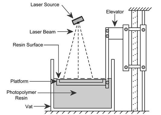
- Stereolithography (SLA) : SLA uses a UV laser to solidify layers of liquid photopolymer resin. The object is built layer by layer on a build platform that moves incrementally downward as each layer is completed.
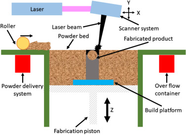
- Selective Laser Sintering (SLS) : SLS involves using a high-powered laser to selectively fuse powdered materials, such as plastics, metals, or ceramics, into a solid structure layer by layer.

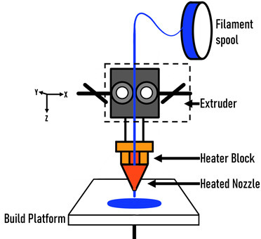
- Fused Deposition Modeling (FDM) : FDM is one of the most popular 3D printing methods. It works by extruding thermoplastic filament through a heated nozzle onto a build platform layer by layer. The material solidifies rapidly to form the desired object.
- Selective Laser Melting (SLM) : SLM is similar to SLS but operates with metal powders. A high-powered laser selectively melts and fuses metallic powders together to build metal parts layer by layer.
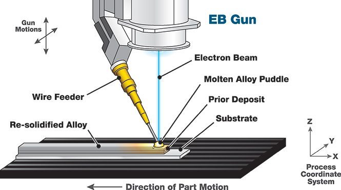
- Electronic Beam Melting (EBM) : EBM is another metal additive manufacturing technique that uses an electron beam instead of a laser to melt and fuse metal powders. It's often used for creating complex metal parts, especially in aerospace and medical applications.
- Binder Jetting : This technique involves selectively depositing a binding agent onto a bed of powder material (metal, sand, ceramic, etc.), layer by layer, to solidify the object. After each layer, a new layer of powder is spread, and the process is repeated until the object is complete.

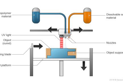
- Material Jetting : Material jetting is similar to inkjet printing but uses materials like resins, waxes, or polymers. Droplets of material are selectively deposited and cured with UV light to form layers.
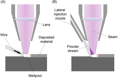
- Directed Energy Deposition (DED) : DED involves focused thermal energy, usually from a laser or electron beam, to melt and fuse materials as they are deposited. It's commonly used for repairing or adding features to existing parts and for building large, complex metal parts.
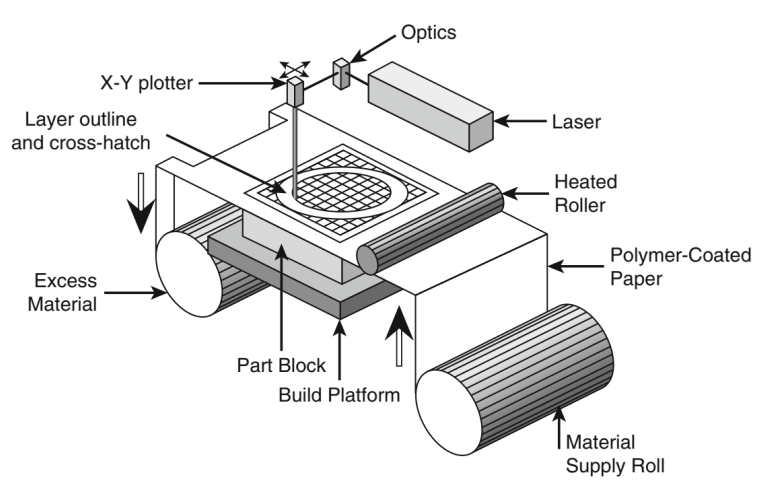
- Sheet Lamination : This method involves bonding together sheets of material, typically paper or metal, using various methods such as adhesive bonding, ultrasonic welding, or friction welding. Each layer is cut to shape and stacked to form the final object.
These are some of the major additive manufacturing techniques, each with its own advantages, limitations, and applications.
For this week's assignment, I began designing a non-subtractive model using Fusion 360. The model is a 30x30x30mm cube with an inner sphere connected to a rod. This design can only be realized using additive manufacturing technology.
After completing the design for printing, the next step is to use a slicer. I opted for PrusaSlicer for this task. To proceed with PrusaSlicer , the file needs to be exported in .stl format.
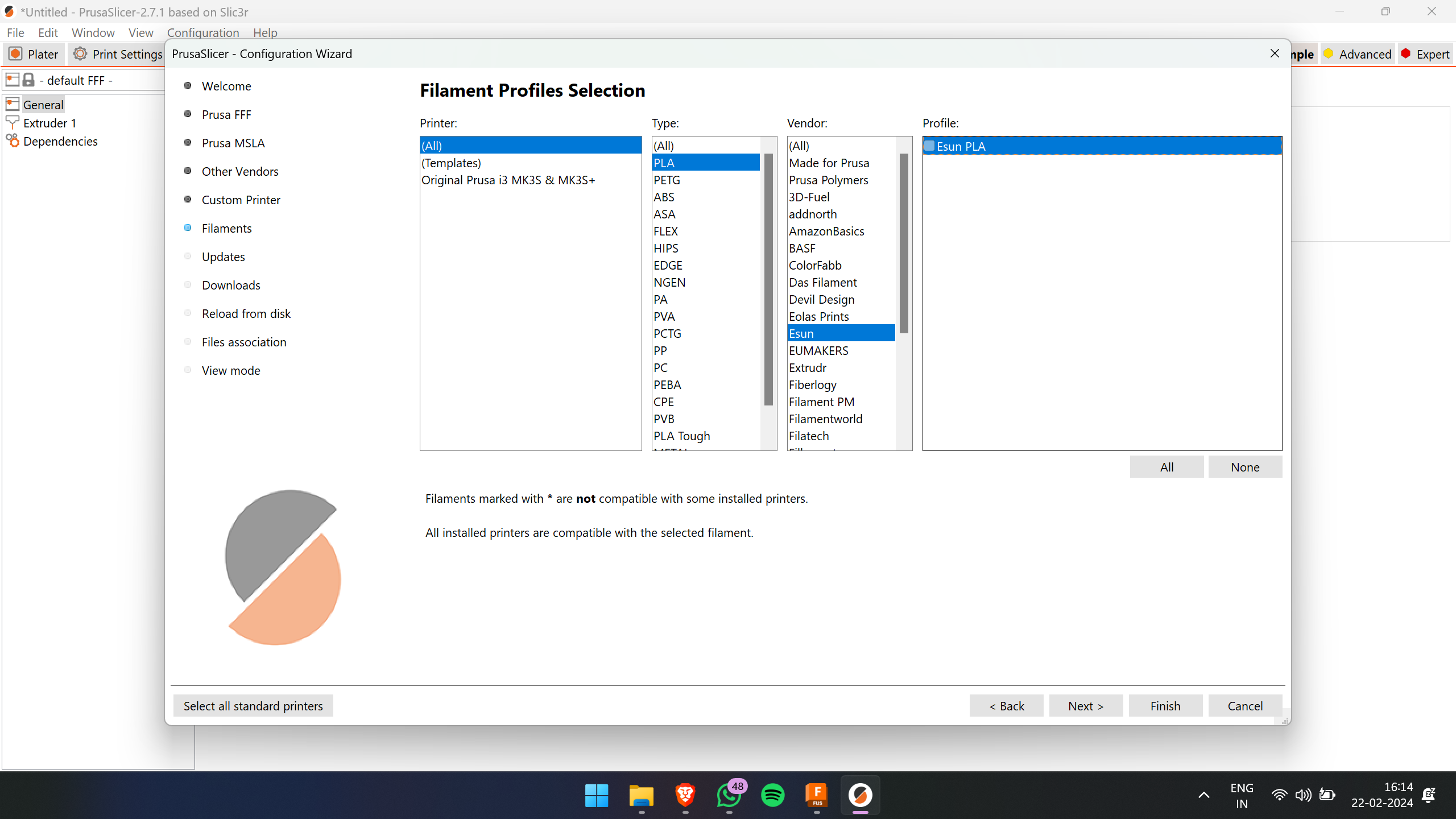
This is the initial interface of PrusaSlicer.
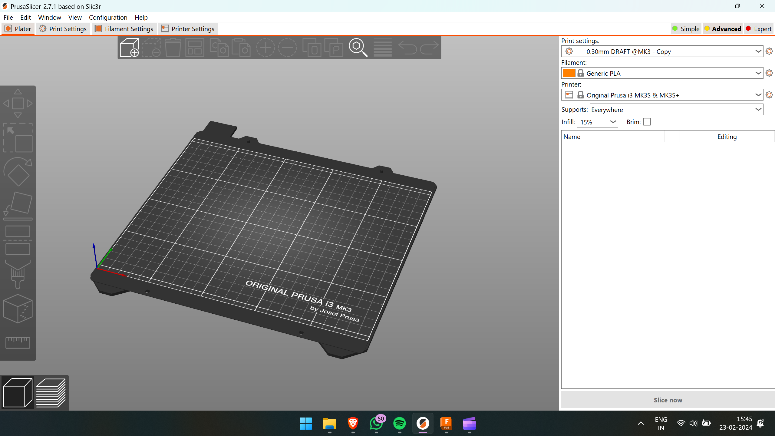
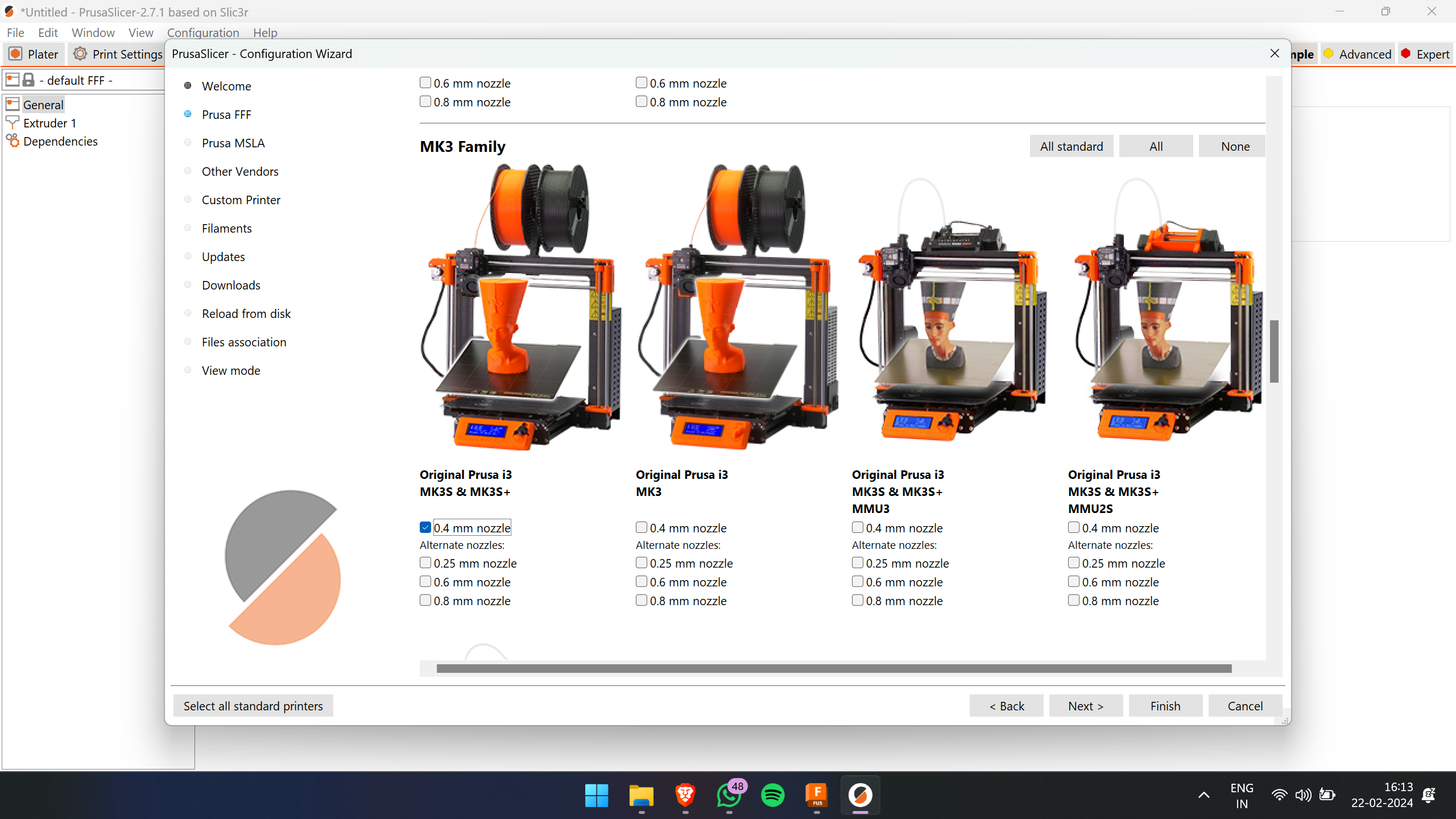
In this slicer, we need to select the material we are using and the specific printer model.
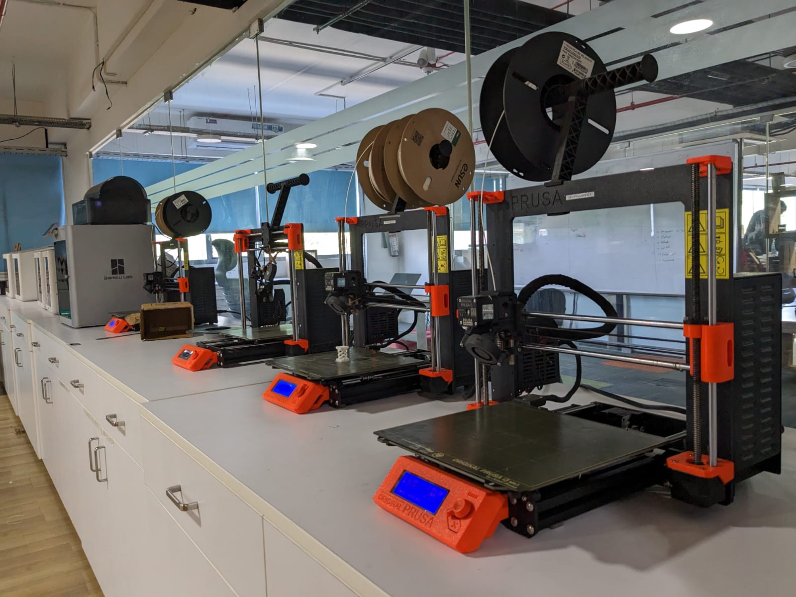
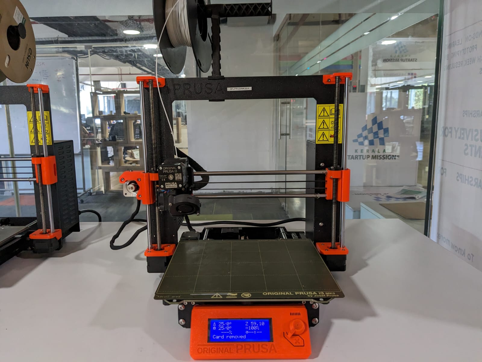
For 3D printing purposes, we were provided with an FDM printer,
specifically the Prusa MK3S model.
Specifications of Prusa MK3S:
- Build Volume: 250x210x210mm
- Nozzle: 0.4mm (default), 0.6mm
- Layer Resolution High : 50 microns
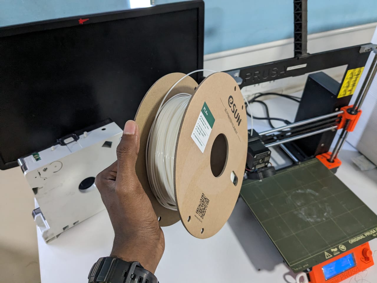
The material used for printing was PLA from the brand eSun.
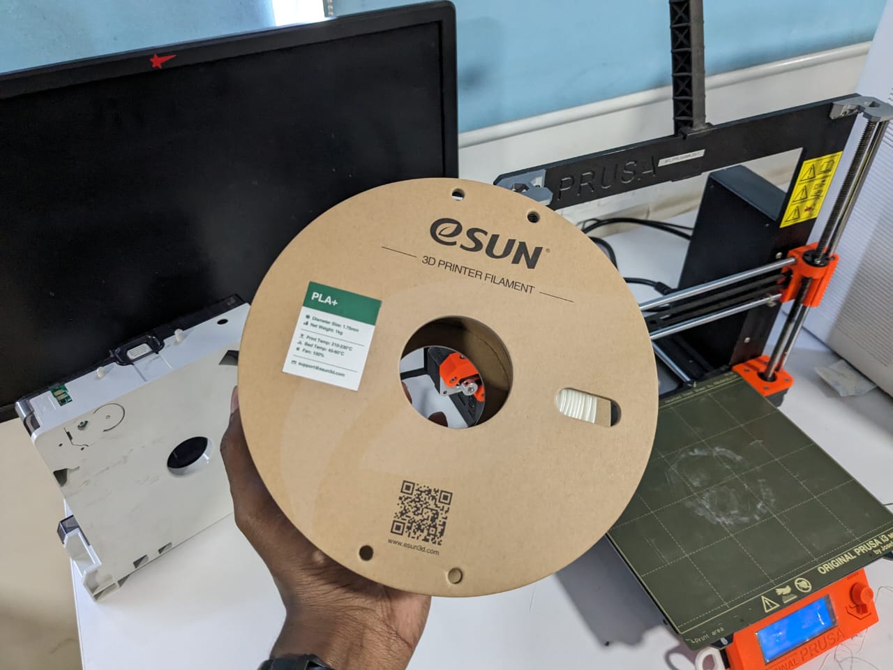
In the slicer software, we need to select the appropriate printer and filament to ensure that predetermined values such as bed temperature, filament print temperature, bed size, etc., are correctly configured for the specific printing setup.
Now, I began exploring the PrusaSlicer software and proceeded to slice the model I had created.
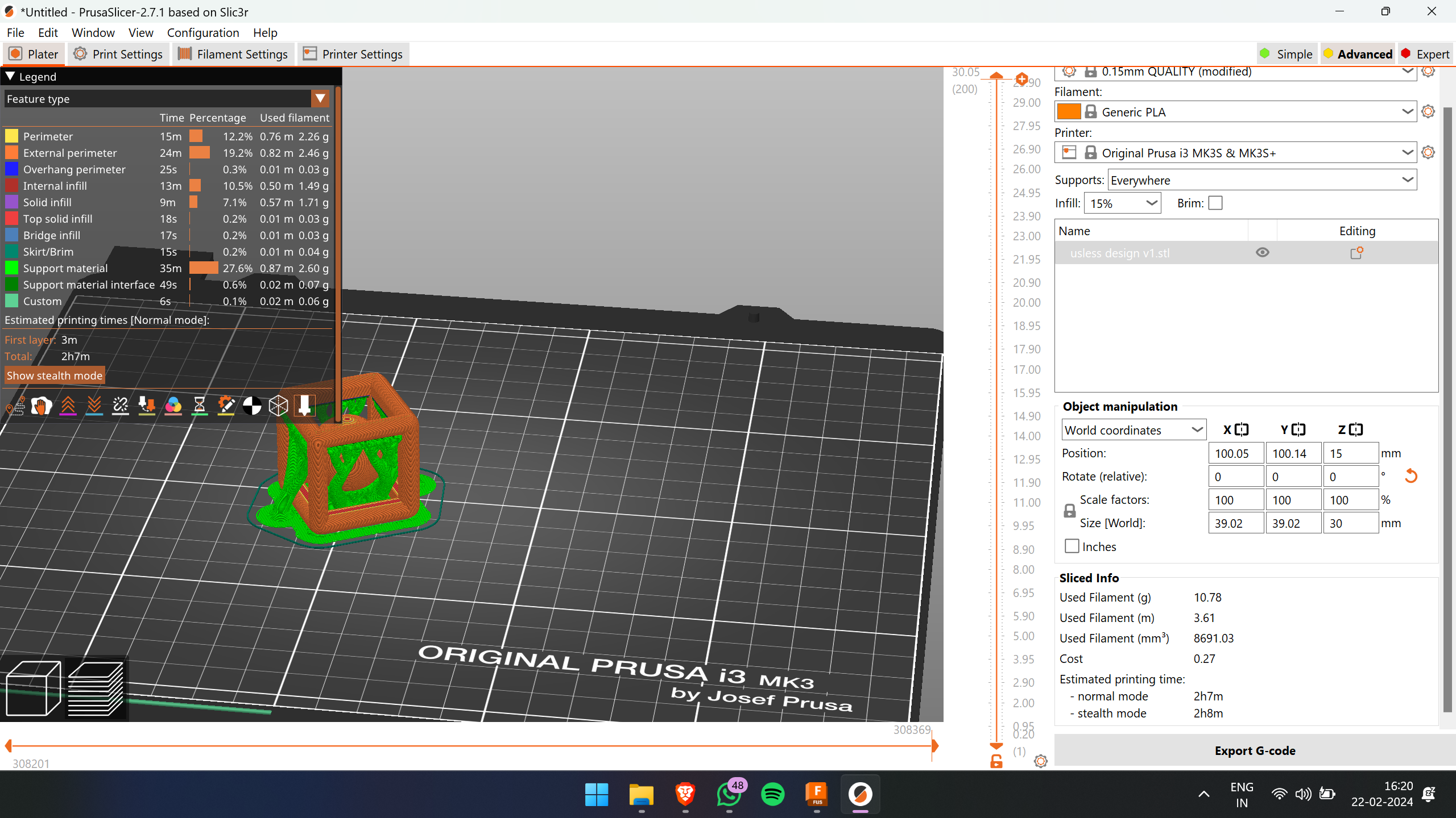
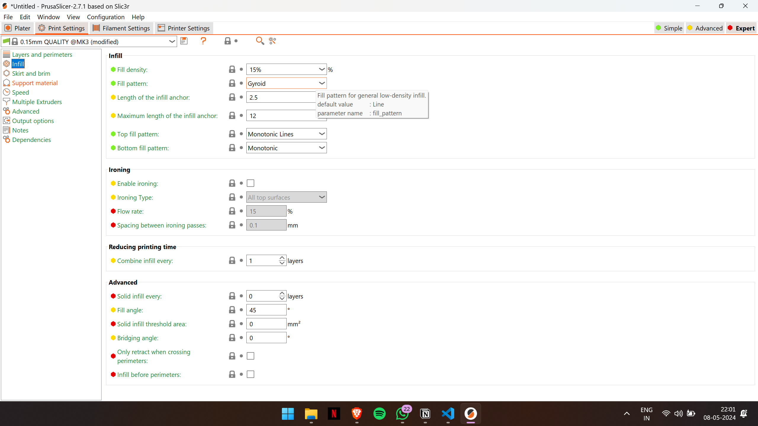
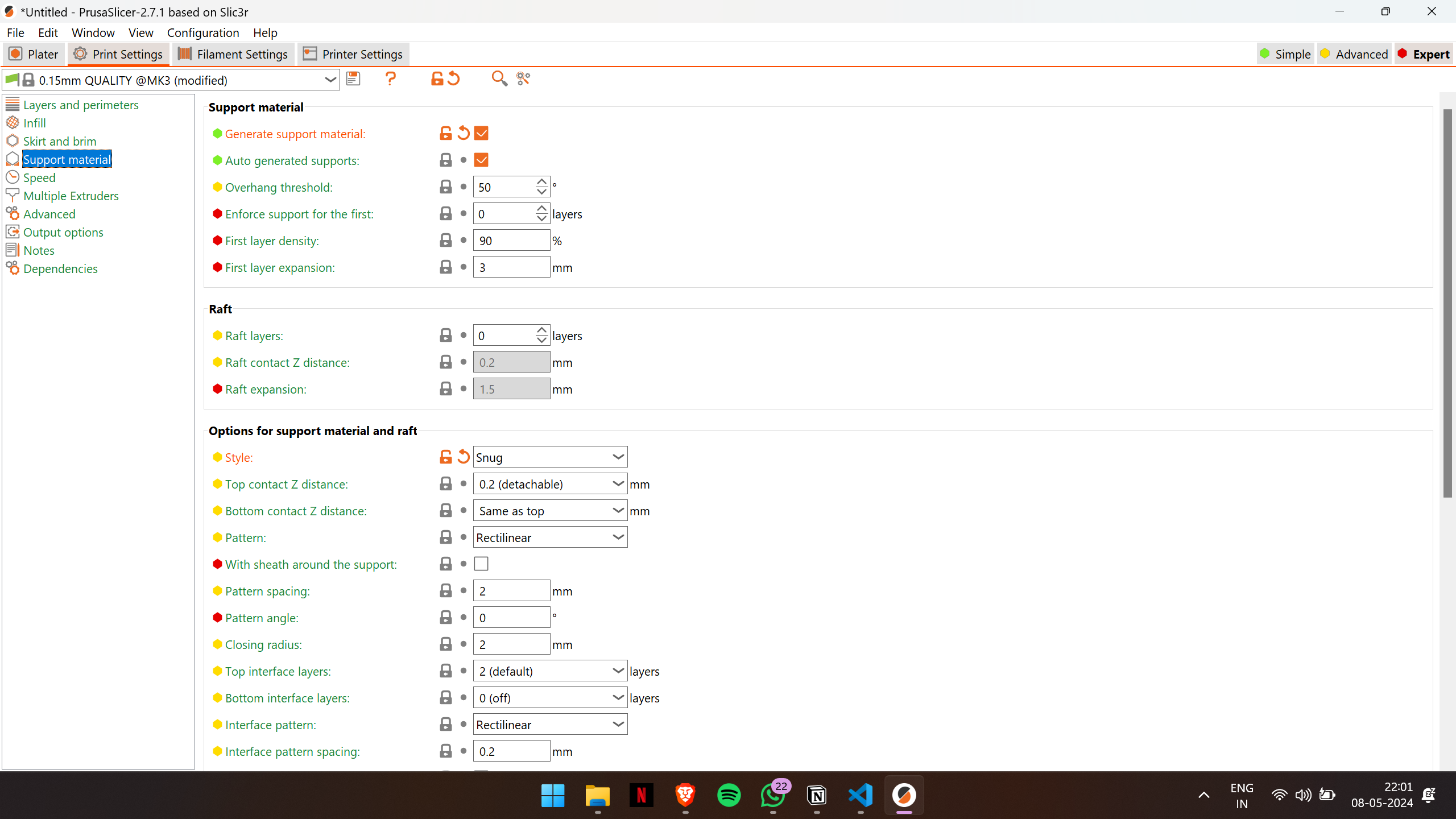
I've applied supports throughout the model and selected the organic pattern, which aids in easy removal of the supports. Additionally, I've set the infill density to 15%, which should be sufficient for this design.
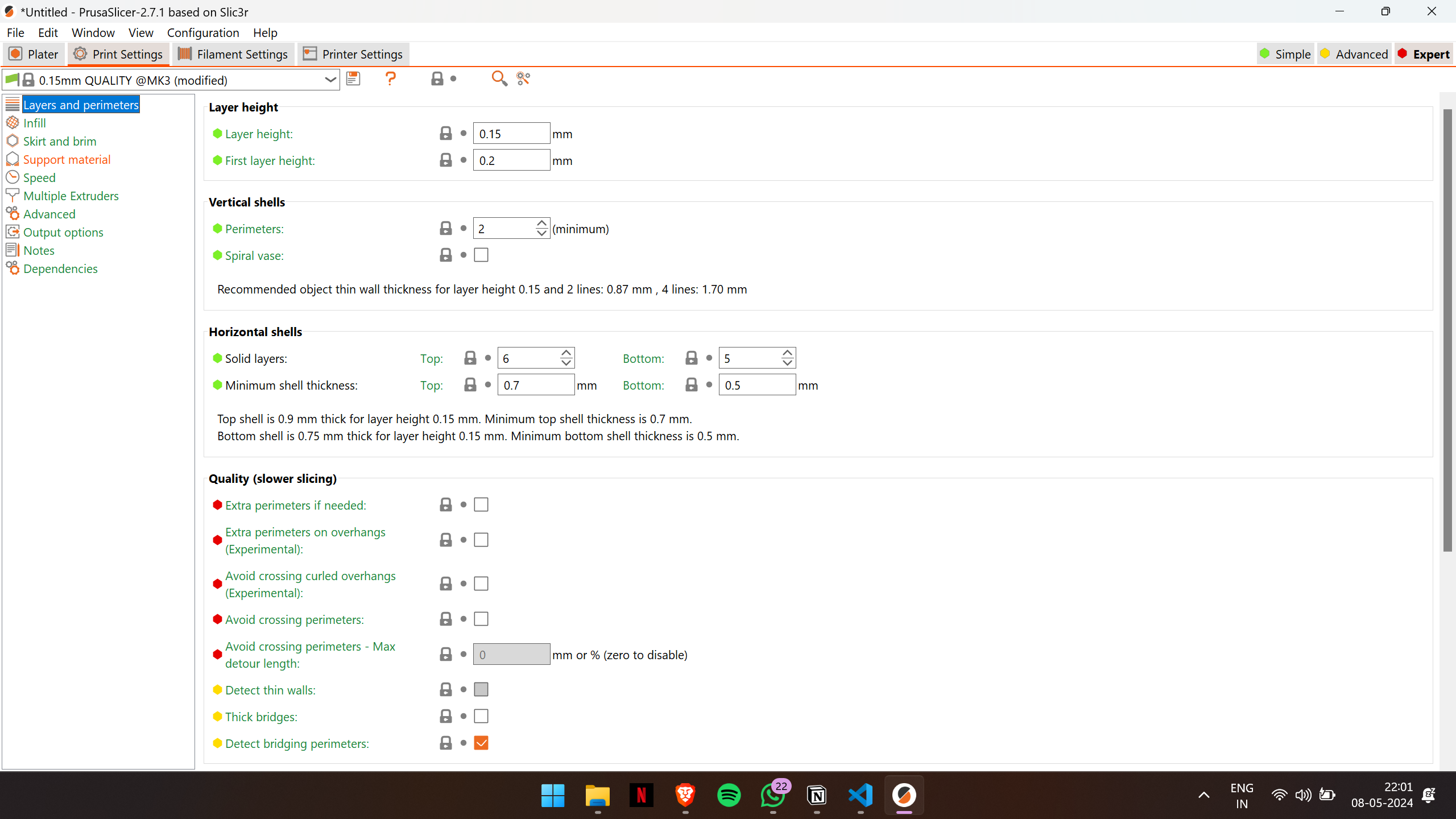
Here are the print settings I utilized for printing this model.
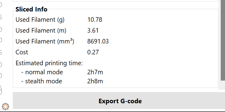
After slicing, the estimated time for the print is 2 hours and 7 minutes
Then, I exported the G-code file and transferred it to the printer to initiate the printing process.
I have experience using Ultimaker Cura software before, but in our lab, we were advised to utilize PrusaSlicer. Upon exploring PrusaSlicer, I found that it offers more customizable options compared to Ultimaker Cura software, making it a superior choice for our printing needs.
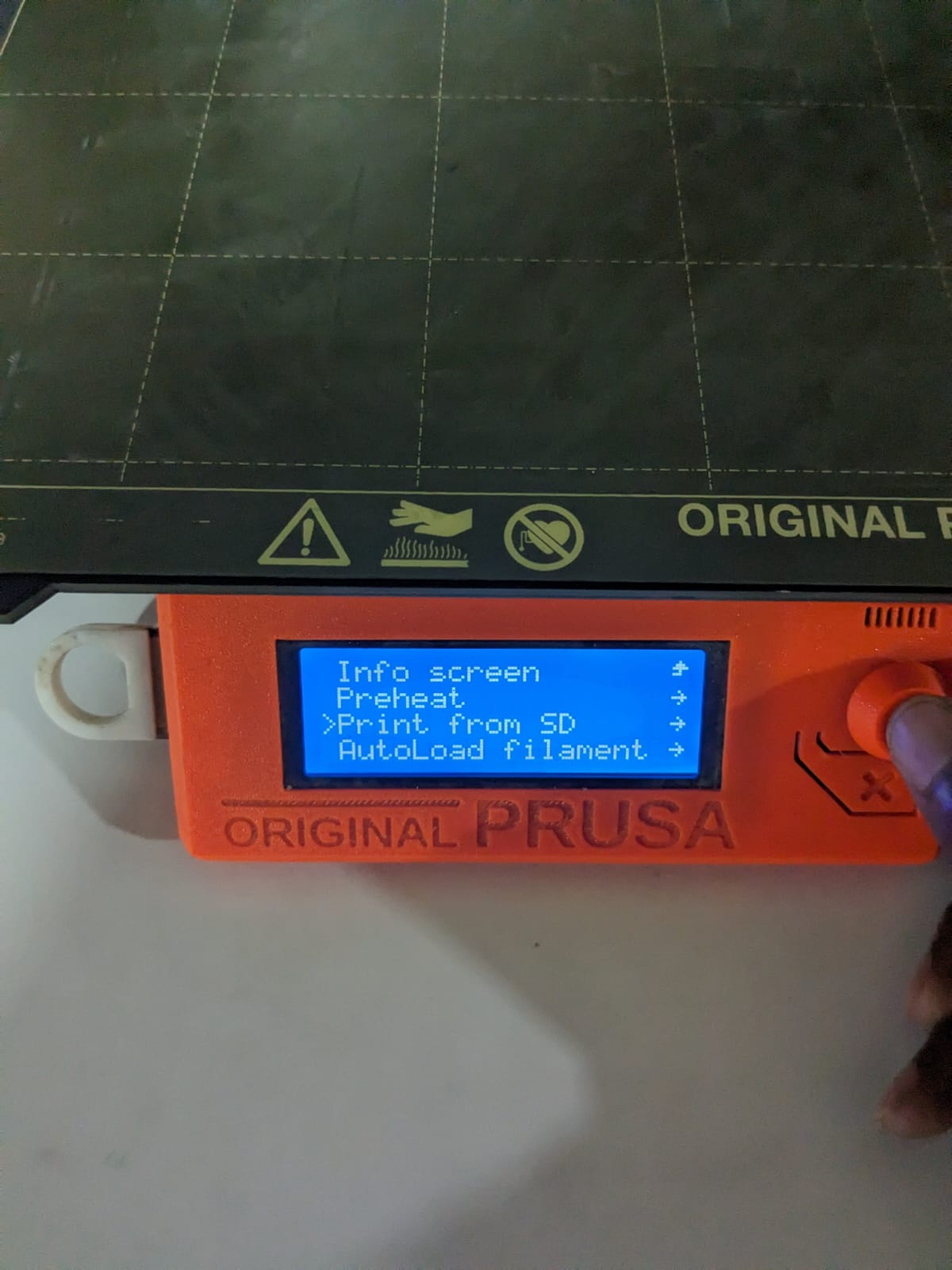
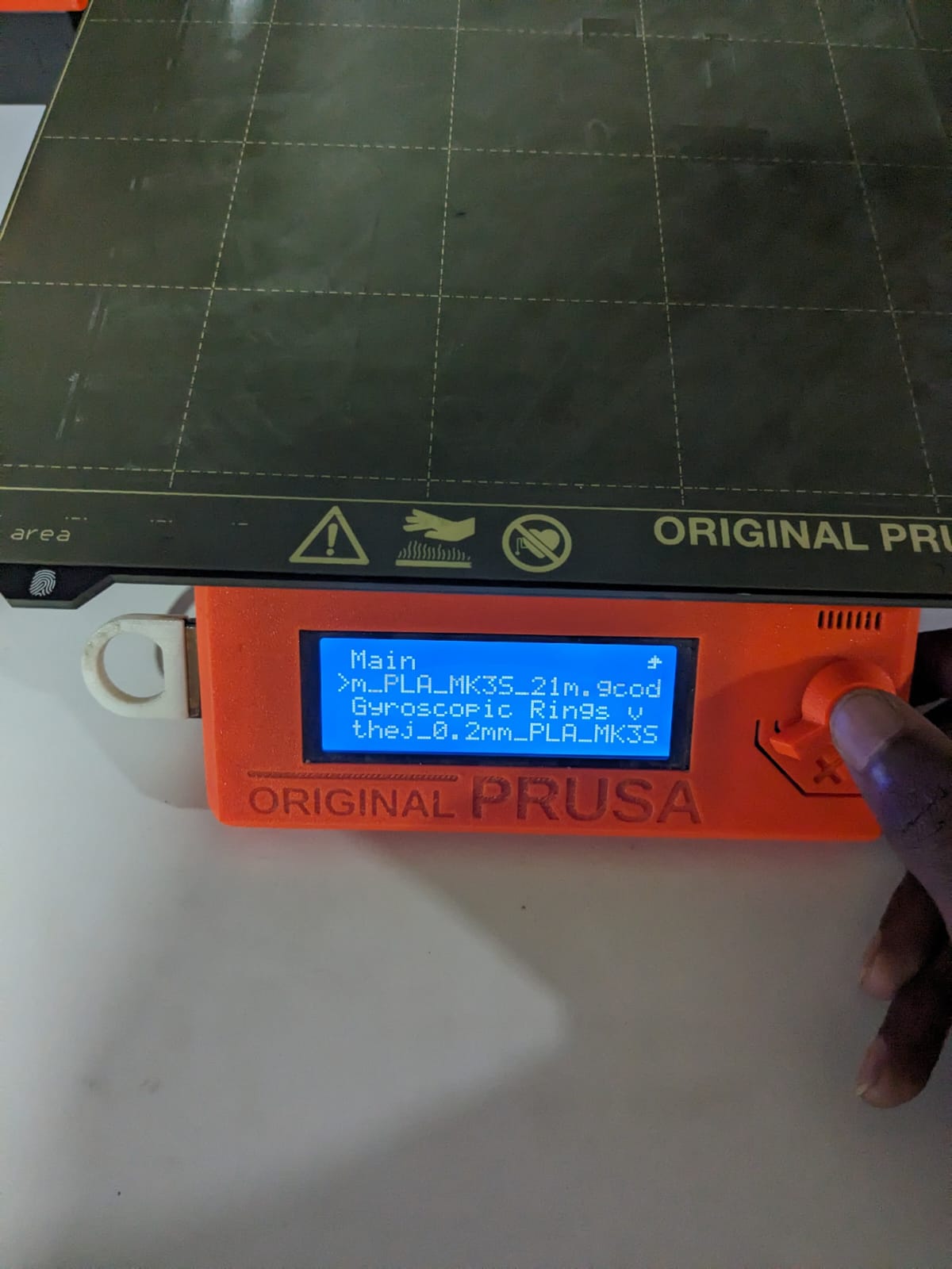
I inserted the SD card into the printer and selected the file from the menu. The printer then began the printing process by heating the bed and the extruder.
After waiting for 2 hours and 7 minutes, the print was completed. In the meantime, I took a break and went for a coffee.🙂
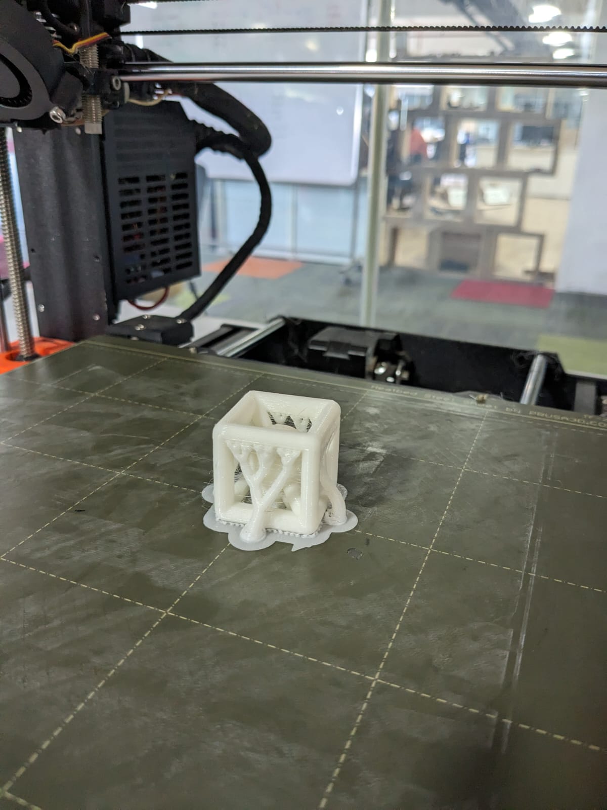
Here is the result after the printing process
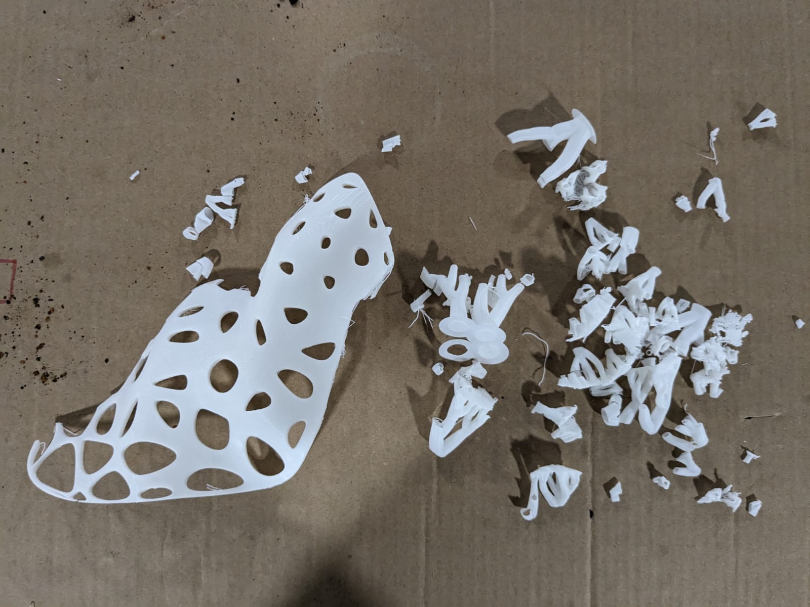
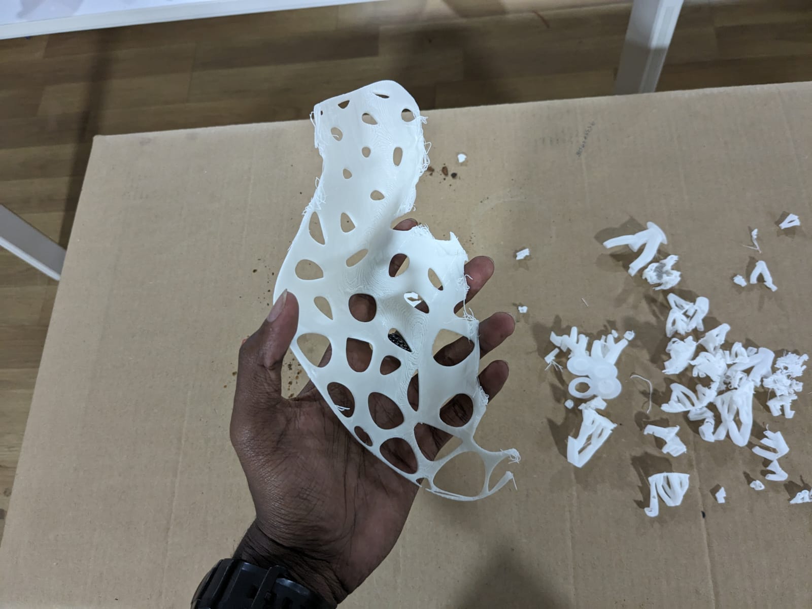
The next step is post-processing, which involves removing the supports and any other finishing touches needed.
In my case, the supports were easily detachable. However, in instances where manual removal is necessary, various sizes of needle-nose pliers can be used for the task.

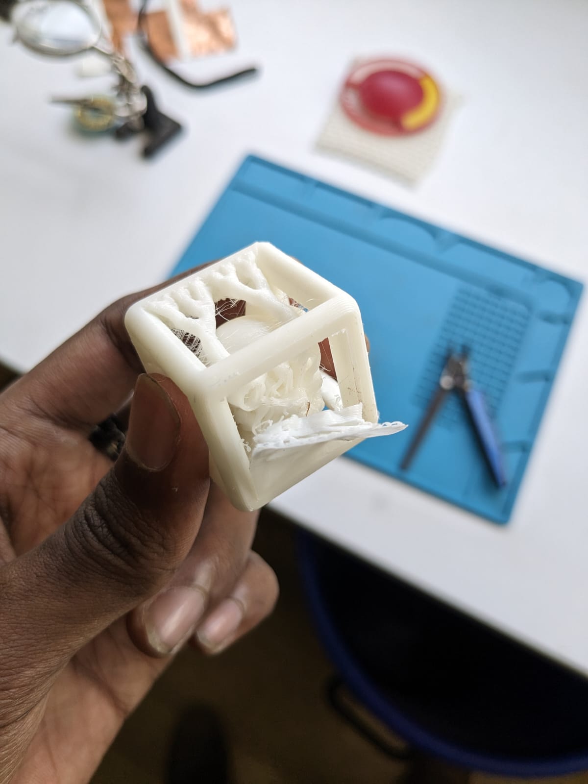
Here is the result after post-processing:
Here is a video where I attempted to remove the supports using needle-nose pliers on another design that was printed in the lab
Here is the outcome after completing the post-processing steps.
3D Scanning
3D scanning entails capturing the physical attributes and shape of an object to generate a digital model. There are various techniques for 3D scanning, including photogrammetry, laser scanning, structured light scanning, and contact scanning. Each method offers unique advantages and limitations, with the selection depending on factors like the object's size, complexity, desired level of detail, and available equipment.
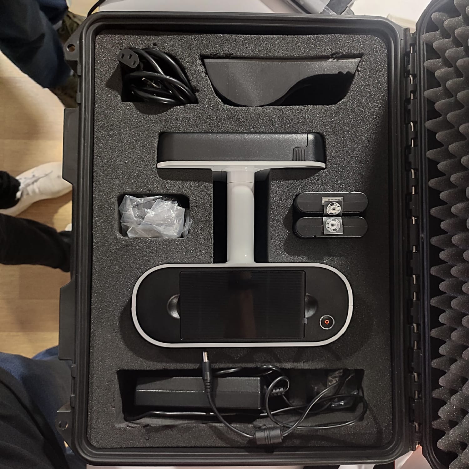
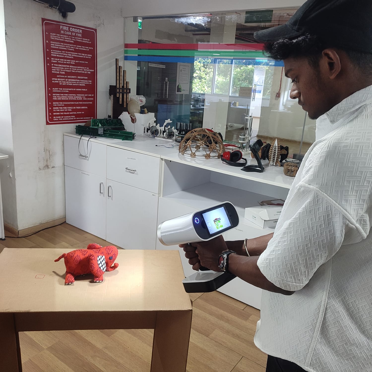
In the lab, we were equipped with the Artec Leo
- Wireless and fully standalone 3D scanner.
- Features the NVIDIA Jetson TX2 processor.
- Includes a 5-inch HD built-in display.
- Equipped with a battery for portability.
- Offers fast, precise, and high-quality data capture.

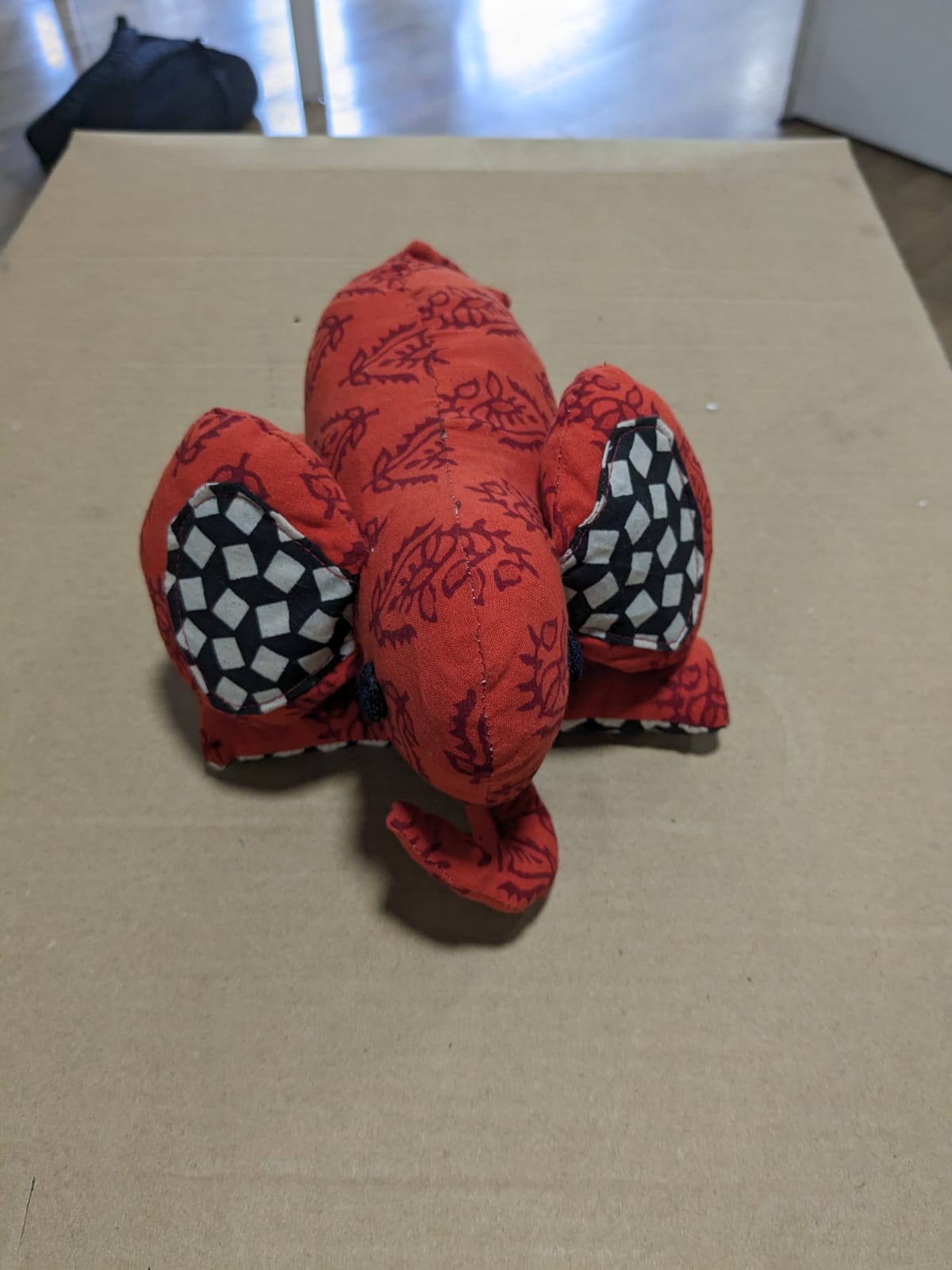
I've selected a small subject for scanning, which is an elephant doll.
The Artec Leo can be powered on with a single press of the button located on the device itself. Once powered on, I initiated a new project by selecting "New Project" on the screen.

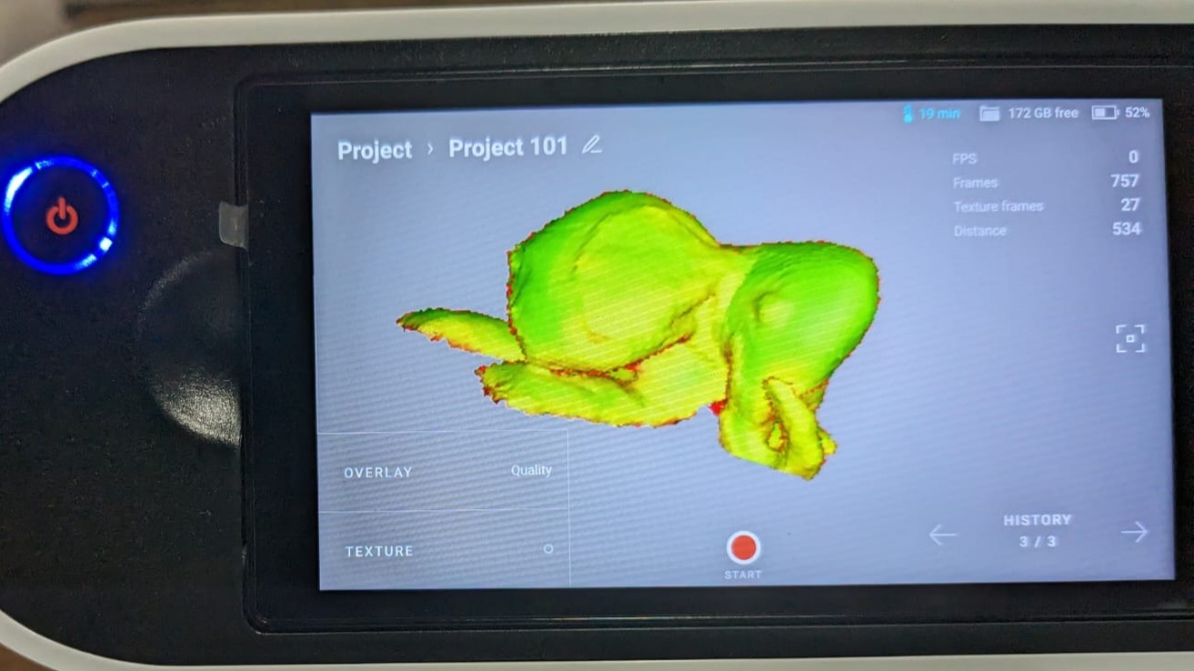
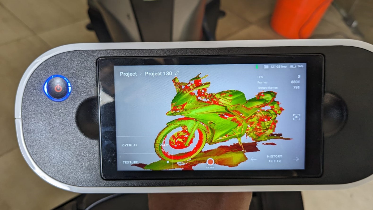
During the scanning process, I observed the feedback provided by Artec Leo. When the scanned surface turned green, it indicated that the surface was successfully registered. If the surface appeared orange, it signaled that it was acceptable for processing. However, if the surface turned red, it indicated that the surface needed to be rescanned to capture additional details.
This is me actively engaged in scanning the object using the Artec Leo.
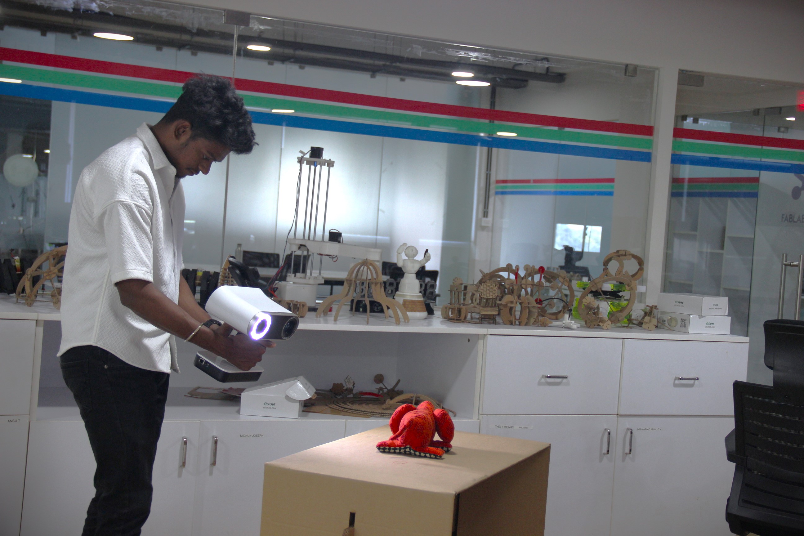
I continued the scanning process diligently until the entire object was successfully scanned and all surfaces turned green, indicating completion.
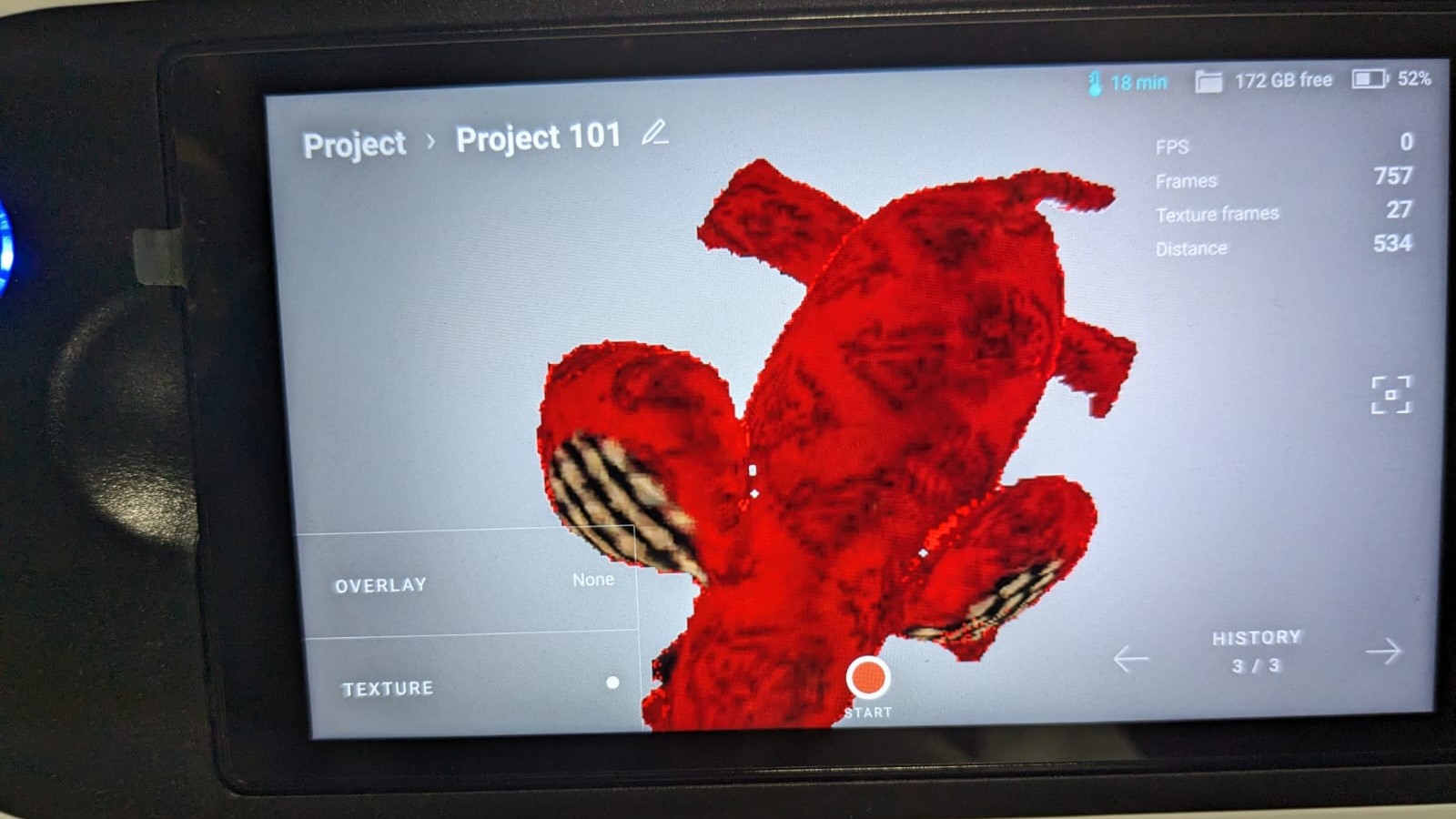
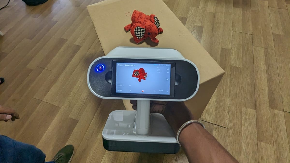
Here is how the scanned object looks with texture applied
I thoroughly enjoyed the scanning process! It was a fascinating experience witnessing the transformation of the physical object into a digital model
By successfully completing the scanning process using the Artec Leo, the next step is post-processing the scanned data using Artec Leo's software.
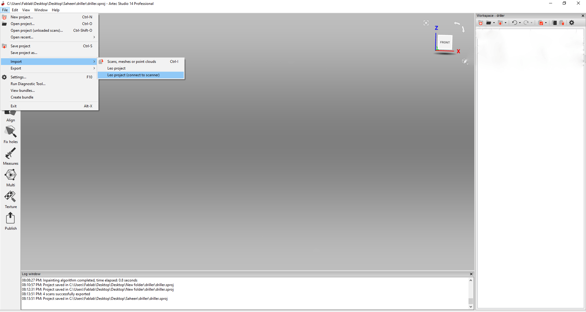
This is the initial interface, and I imported my data into the software.
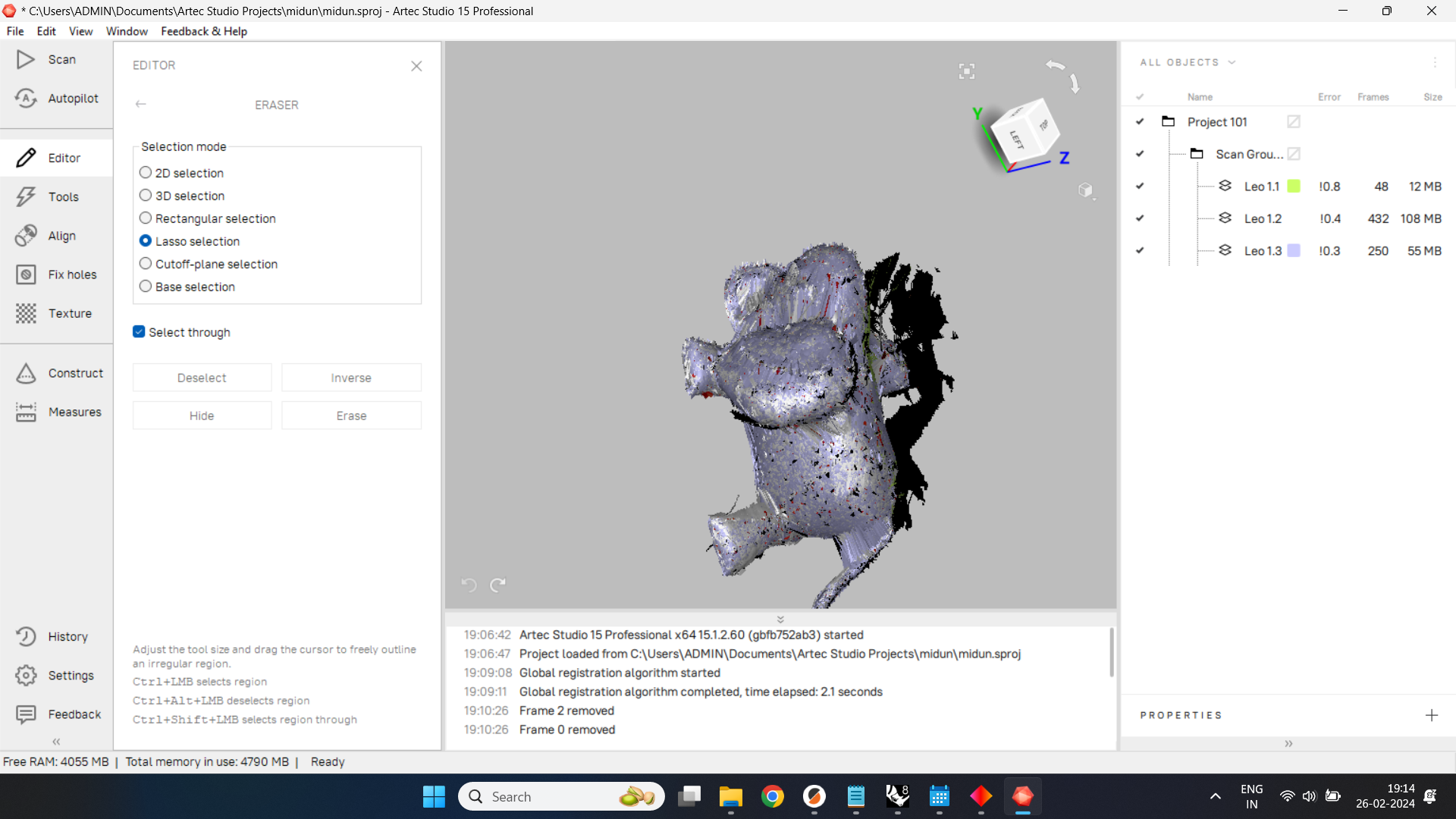
After importing the file, I began removing the unwanted surfaces that are not required for the model. I accessed the editor menu and utilized various options such as lasso selection, 2D selection, 3D selection, etc.

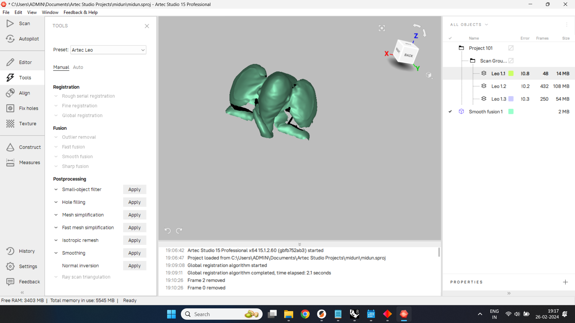
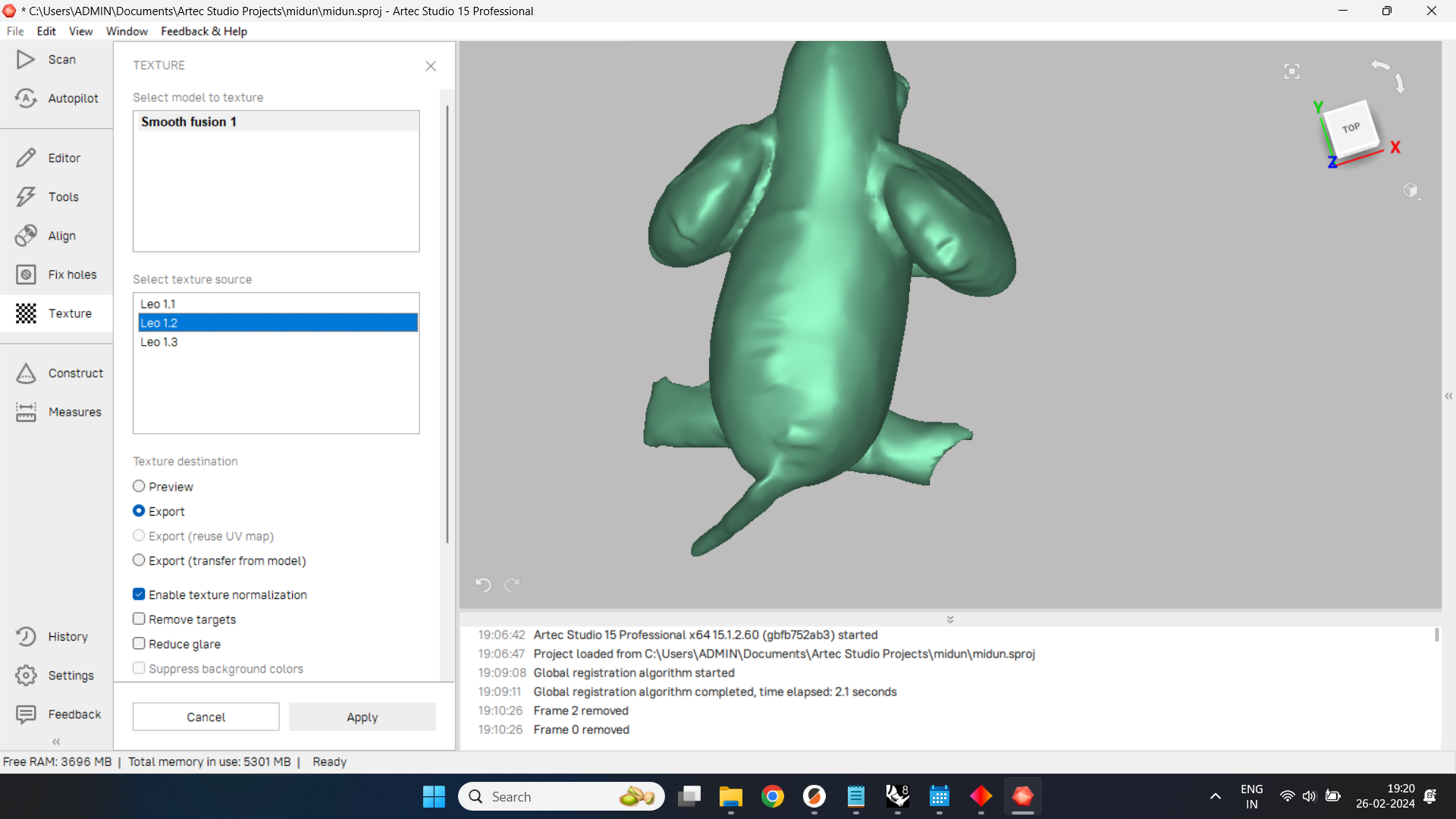
Next, I navigated to the tools menu and selected global registration, as my scan was done in one go. Then, to meet my requirements, I applied a smooth fusion since accuracy wasn't crucial in this case. Finally, in the post-processing section, I experimented with various options to enhance the appearance of my scan.
Afterward, I addressed any holes in the scan by navigating to the "Fix Holes" menu. Here, I selected the holes that needed fixing and clicked on the "Fill Holes" option, which automatically repaired the holes in the scan.
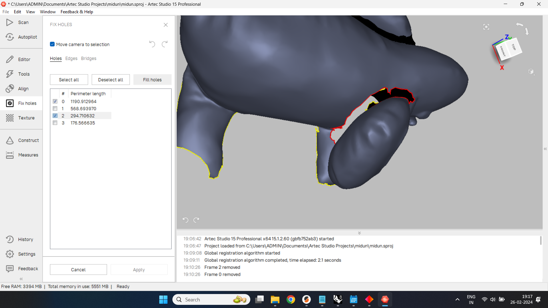

Sometimes, the automatic repair of holes may not work as expected. In such cases, manual fixing is required. I navigated to the "Construct" menu and manually addressed the fixing. However, in my case, the "Fix Holes" menu successfully accomplished the task.
After fixing the holes, the scan is nearly complete. Now, it's time to apply the correct texture.
Additionally, adjustments can be made to brightness, contrast, saturation, and gamma radiation to meet specific requirements. Once adjustments are made according to our preferences, the file can be exported.
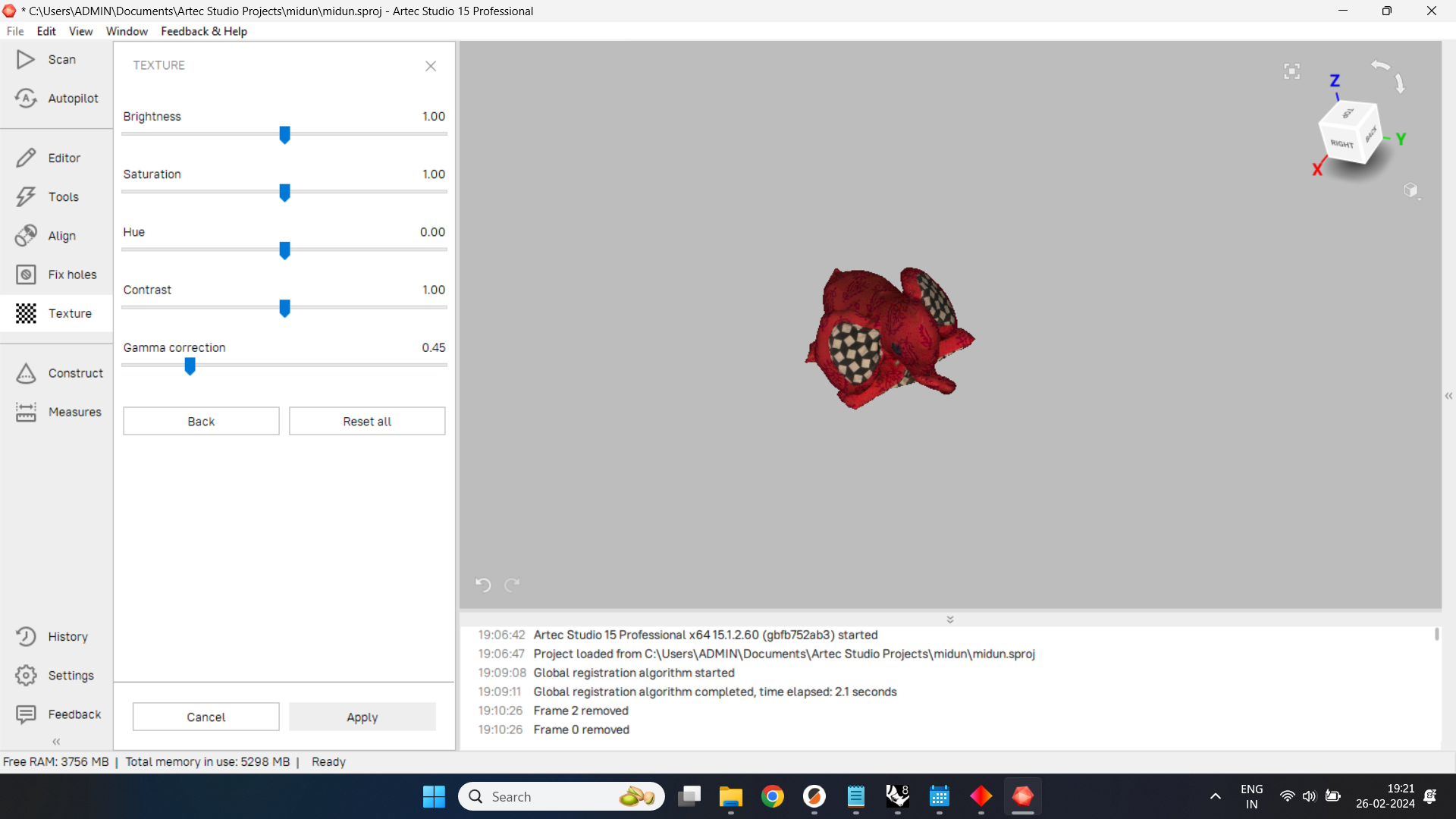
I exported the final model as a '.obj' file, ensuring that the texture was included in the export.
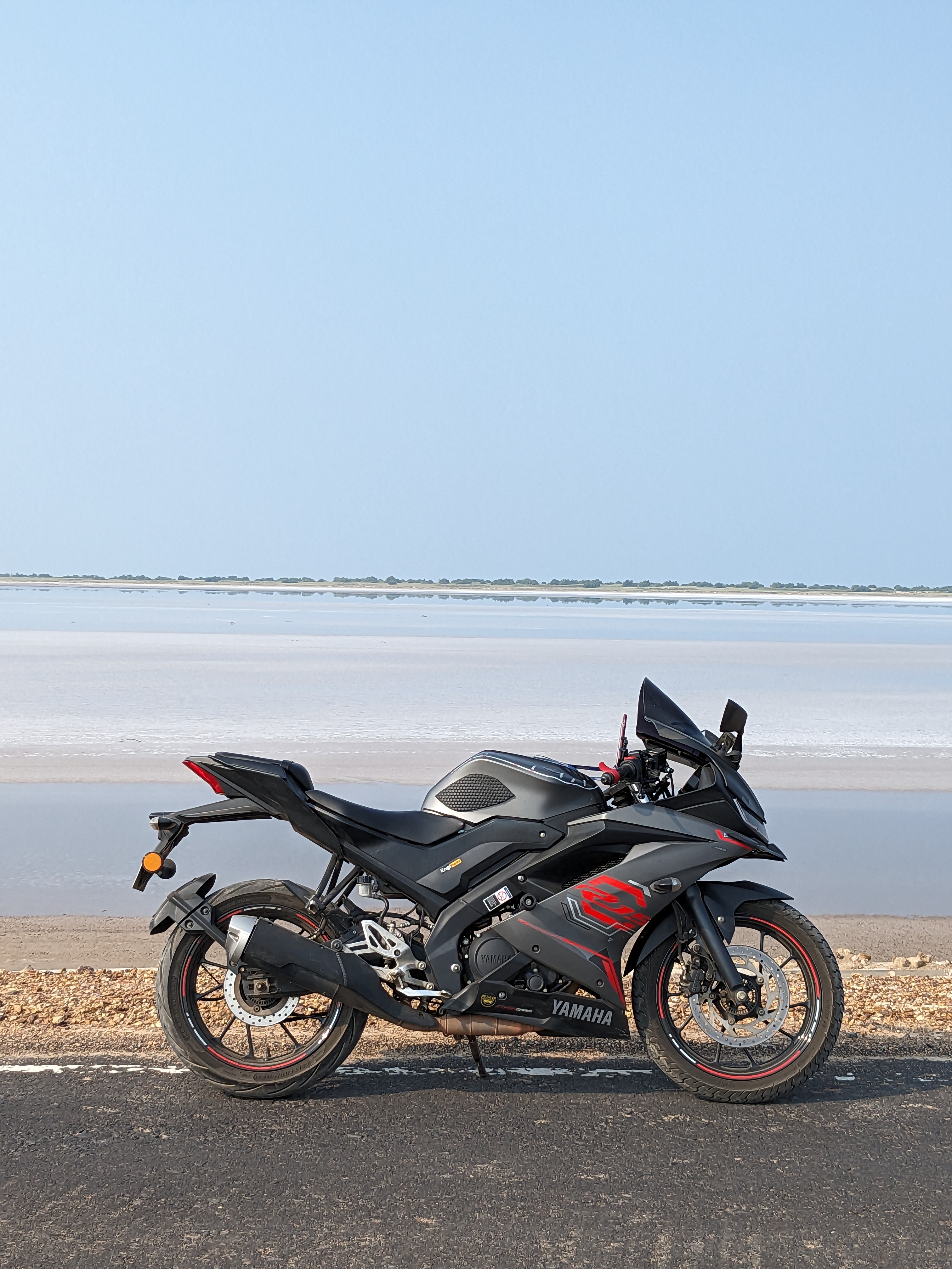
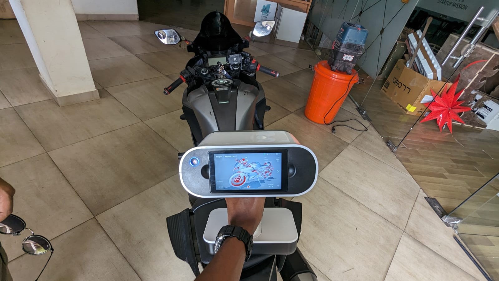
Now, I've decided to scan my motorcycle to explore the capabilities of the Artec Leo.
This is my motorcycle.
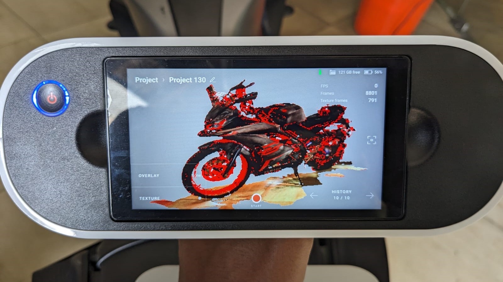
I began scanning my motorcycle, and here I am immersed in the scanning process.
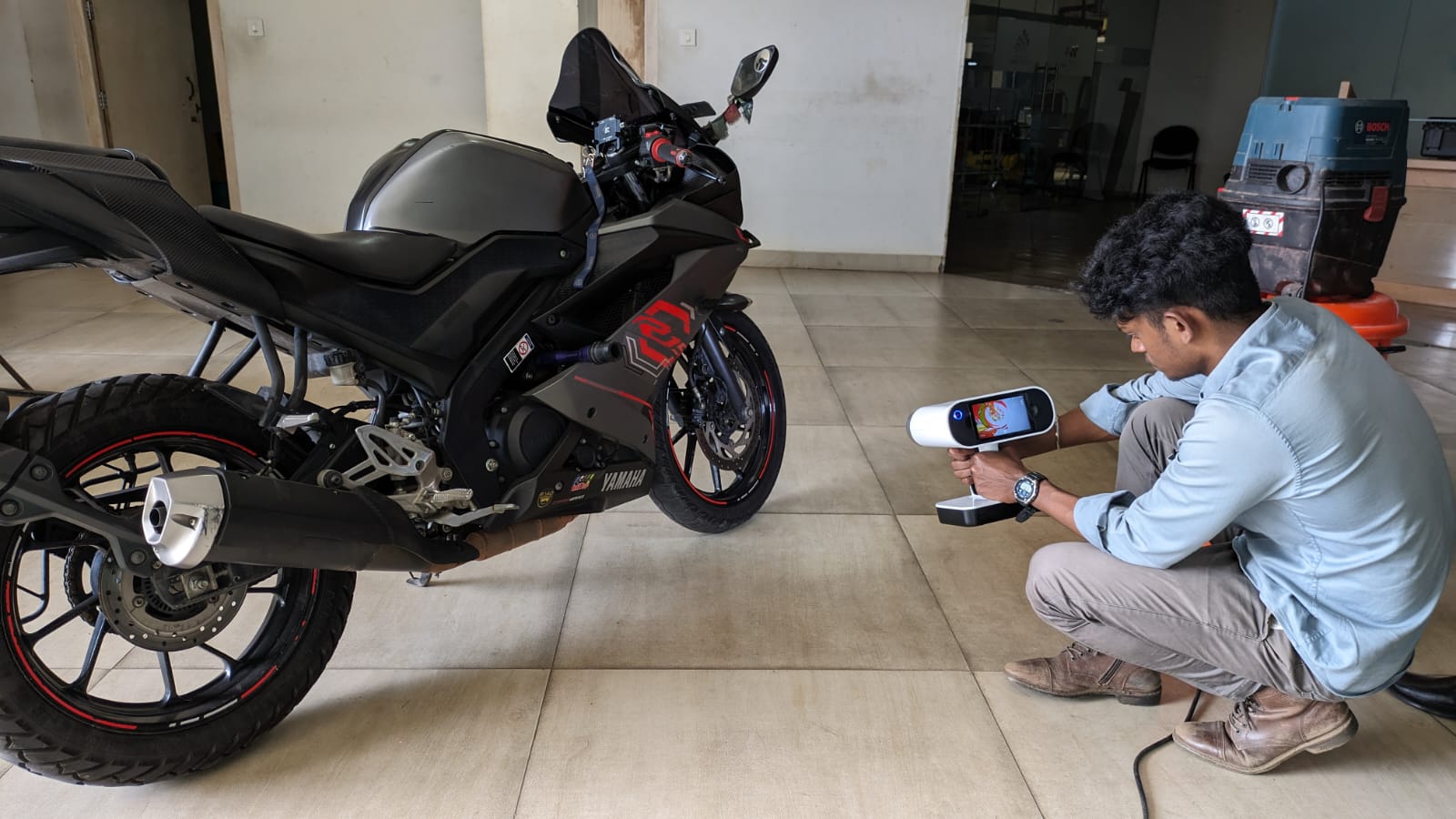
After scanning, here are the results.
After the scanning process, I proceeded to the post-processing stage, which involved similar steps as before. Here are the results of the post-processing process.